Ultra-Low-Voltage Buck–Boost Converter (0.3 V to 5 V)
- EN
- ZH-CN
Table of Contents
#
Chip Selection
I took on a challenging requirement: convert 0.5 V to 2.0 V.
A conventional boost–buck approach couldn’t meet this because a typical diode drop is about 0.7V while the source only provides 0.5V.
Most converter ICs on the market need around 0.9V to start up, which this source doesn’t meet.
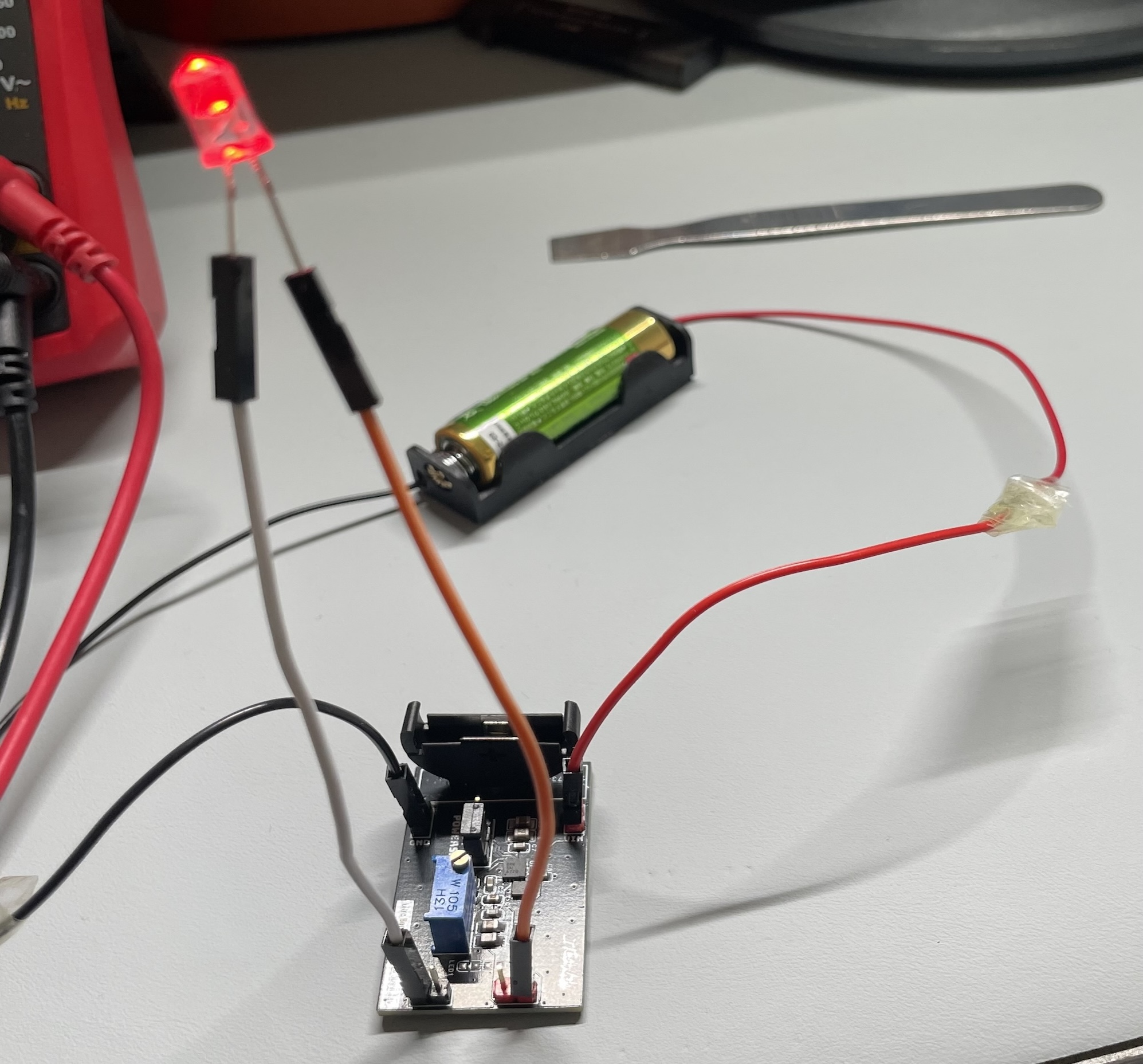
After quite a bit of searching, I found the TPS61200, which supports 0.3–5.5V input and can output 1.8–5.5V (adjustable or fixed).
#
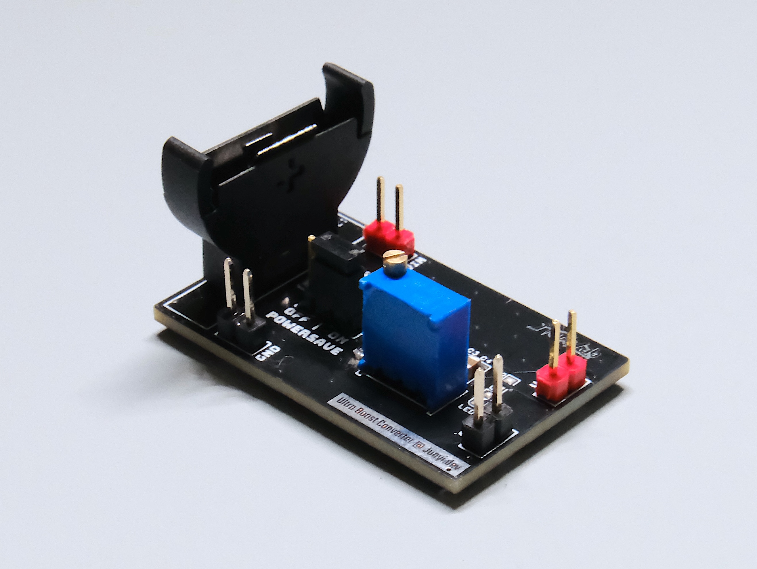
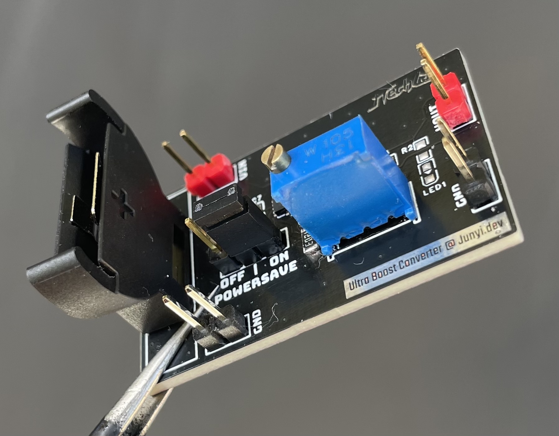
PCB Design
Big thanks to my mentor JYF, who gave me lots of guidance and turned my PCB around.
For the first revision, I followed these app notes: Supplying TPS61200 With a Single Solar Cell and Using TPS61200 as WLED Driver. JYF taught me many power-supply layout tips, such as:
- Use keep-out regions when copper-pouring to avoid creating “antennas”.
- Near any “antenna,” add vias so interference returns cleanly to ground.
- Size the PCB in 5 mm increments to make enclosures easier.
- Stencils are cheaper to order on Taobao.
Horizontal sockets are awkward; vertical ones work better.- …
His help was key to making this project succeed on the first try.
(By the way, I skipped the MPP circuit. That can demand about 1A from the source for up to 20ms, which is effectively a short for some fuel cells and can shorten their lifespan.)
#
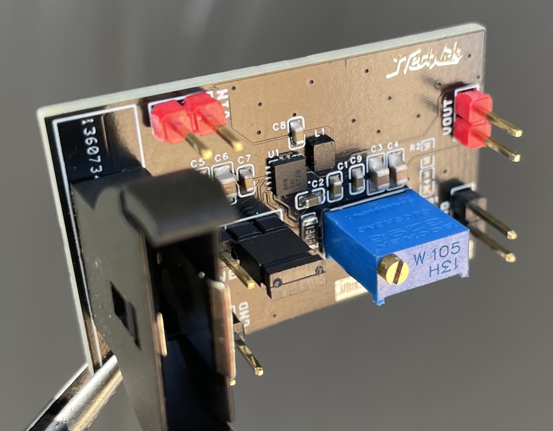
Soldering
This was my first time hand-soldering a QFN. I ruined one PCB before getting it right, but the final result came out great.
My 0805 soldering used to look ugly; now 0603 is no problem either. If I ever get laid off, I can go tighten screws in a factory.
Compared with before, I made a lot of progress this round (see my earlier board here: Ultra‑mini ESP8266 dev board).
#
Photos
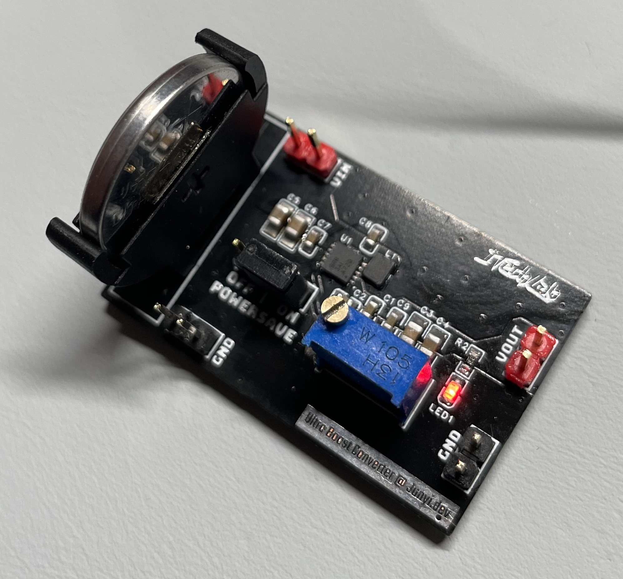
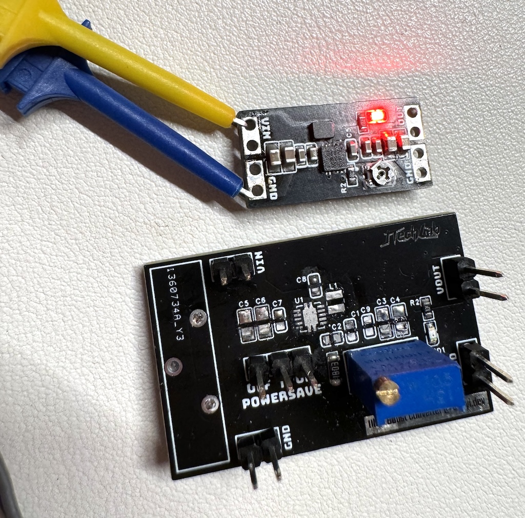
Update on 2024‑06‑15:
- Removed the pin header
- Removed the coin‑cell holder
- Removed the POWERSAVE option (enabled by default)
- Improved adjustable output range from 0.5–3.3V to 0.5–5.5V
- Switched to a 3mm potentiometer; shorter feedback path